Shortwave Direction finding

Operation RAFTER
RAFTER was a code name for the MI5 radio receiver detection technique, mostly used against clandestine Soviet agents and monitoring of domestic radio transmissions by foreign embassy personnel from the 1950s on.
Explanation
Since most radio receivers are of the superhet design, they typically contain local oscillators which generate a radio frequency signal in the range of 455 kHz above or sometimes below the frequency to be received. There is always some radiation from such receivers, and in the initial stages of RAFTER, MI5 simply attempted to locate clandestine receivers based on picking up the superhet signal with a quiet sensitive receiver that was custom built. This was not always easy because of the increasing number of domestic radios and televisions in people's homes.
By accident, one such receiver for MI5 mobile radio transmissions was being monitored when a passing transmitter produced a powerful signal. This overloaded the receiver, producing an audible change in the received signal. Quickly the agency realized that they could identify the actual frequency being monitored if they produced their own transmissions and listened for the change in the superhet tone.
Soviet transmitters
Since Soviet short-wave transmitters were extensively used to broadcast messages to clandestine agents, the transmissions consisting simply of number sequences read aloud and decoded using a one-time pad, it was realized that this new technique could be used to track down such agents. Specially equipped aircraft would fly over urban areas at times when the Soviets were transmitting, and attempt to locate receivers tuned to the Soviet transmissions.
Tactics
Like many secret technologies, RAFTER's use was attended by the fear of over-use, alerting the quarry and causing a shift in tactics which would neutralize the technology. As a technical means of intelligence, it was also not well supported by the more traditional factions in MI5. Its part in the successes and failures of MI5 at the time is not entirely known.
In his book Spycatcher[1] , MI5 officer Peter Wright related one incident in which a mobile RAFTER unit in a van, or panel truck, was driven around the backstreets in an attempt to locate a receiver. What with interference and the effects of large metal objects in the surroundings, such as lamp posts, this proved futile. Later, however, they concluded that the receiver itself had been mobile, and may at one point have been parked next to the van, hidden by a high fence.
References
1. ^ Spycatcher: The Autobiography of a Senior Intelligence Officer, by Peter Wright, 1987.
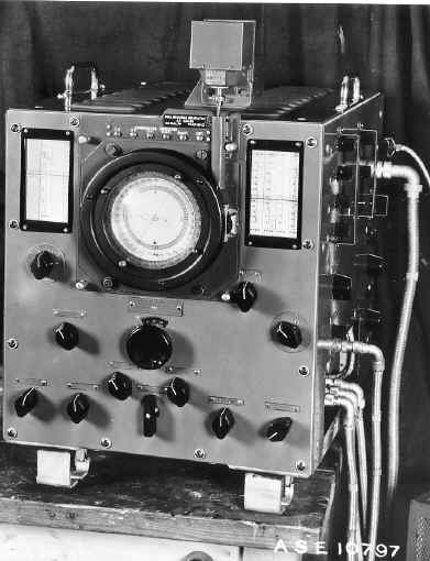
High frequency direction finding, usually known by its abbreviation HF/DF (nicknamed

huff-duff, pronounced "aitch eff dee eff") is the common name for a type of radio direction finding employed especially during the two World Wars.
The idea of using two or more radio receivers to find the bearings of a radio transmitter and with the use of simple triangulation find the approximate position of the transmitter had been known and used since the invention of wireless communication. The general principle is to rotate a directional aerial and note where the signal is strongest. With simple aerial design the signal will be strongest when pointing directly towards and directly away from the source, so two bearings from different positions are usually taken, and the intersection plotted. More modern aerials employ uni-directional techniques.
HF/DF was used by early aviators to obtain bearings of radio transmitters at airfields by rotatable aerials above the cockpit, and during World War I shore installations of all protagonists endeavoured to obtain information about ship movements in this way. The requirement both to tune a radio and rotate an aerial manually made this a cumbersome and slow business, and one which could be evaded if the radio transmission were short enough. Films depicting World War II spies transmitting covertly will sometimes show detection vans attached to patrols performing this activity.
Finding the location of radio and radar transmitters is one of the fundamental disciplines of Signal Intelligence SIGINT. In the World War II context, Huff Duff applied to direction-finding of radio communications transmitters, typically operating at high frequency (HF). Modern direction finding of both communications and noncommunications signals covers a much wider range of frequencies.

Within communications intelligence (COMINT), direction finding is part of the armoury of the intelligence analyst. Sister disciplines within COMINT include cryptanalysis, the analysis of the content of encrypted messages, and traffic analysis, the analysis of the patterns of senders and addressees. While it was not a significant World War II tool, there are a variety of Measurement and Signal Intelligence (MASINT) techniques that extract information from unintentional signals from transmitters, such as the oscillator frequency of a superheterodyne radio receiver.

Along with ASDIC (sonar), Ultra code breaking (COMINT) and radar, "Huff-Duff" was a valuable part of the Allies' armoury in detecting German U-boats and commerce raiders during the Battle of the Atlantic.
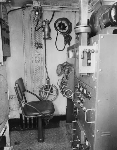
The Royal Navy designed a particularly sophisticated apparatus that could take bearings on the high frequency radio transmitters employed by the German Kriegsmarine in World War II. There were severe technical problems of engineering effective high frequency direction finding systems for operation on ships, mainly due to the effects of the superstructure on the wavefront of arriving radio signals. However, these problems were overcome under the technical leadership of the Polish engineer Waclaw Struszyn'ski, working at the Admiralty Signal Establishment.
Many shore based installations were constructed around the North Atlantic and whenever a U-boat transmitted a message, "Huff-Duff" could get bearings on the approximate position of the boat. Because it worked on the electronic emission and not the content of the message, it did not matter that the content was encrypted using an Enigma machine. This information was then transmitted to convoys at sea, and a complex chess game developed as Royal Navy controllers tried to manoeuvre wide convoys past strings of U-Boats set up by the Kriegsmarine controllers.
A key feature of the British "Huff-Duff" was the use of an oscilloscope display and fixed aerial which could instantaneously reveal the direction of the transmission, without the time taken in conventional direction finding to rotate the aerial -- U-boat transmissions were deliberately kept short, and it was wrongly assumed by the U-boat captains that this would avoid detection of the sender's direction.
Another feature was the use of continuously motor-driven tuning, to scan the likely frequencies to pick up and sound an automatic alarm when any transmissions were detected.
In 1942 the allies began to install Huff-Duff on convoy escort ships, enabling them to get much more accurate triangulation fixes on U-boats transmitting from over the horizon, beyond the range of radar. This allowed hunter-killer ships and aircraft to be dispatched at high speed in the direction of the U-boat, which could be illuminated by radar if still on the surface and by ASDIC if it had dived. It was the operation of these technologies in combination which eventually turned the tide against the U-boats.
Battle of Britain
During the Battle of Britain the Royal Air Force (RAF) deployed an Identification Friend or Foe (IFF) system codenamed "pipsqueak". RAF fighters had a clockwork mechanism that regulated the broadcast of a signal over an HF channel for fourteen seconds of every minute. Each Fighter Command sector had Huff-Duff receiving stations that would monitor the "pipsqueak" broadcasts and telephone the bearings back to the sector control rooms where they could be triangulated and the squadron's location plotted.

Wullenweber
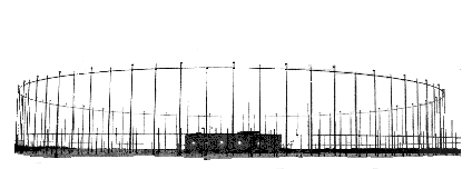
The Wullenweber (the original name introduced by Dr. Hans Rindfleisch was Wullenwever) is a type of Circularly Disposed Antenna Array (CDAA) sometimes referred to as a Circularly Disposed Dipole Array (CDDA). It is a large circular antenna array used for radio direction finding. It was used by the military to triangulate radio signals for radio navigation, intelligence gathering and search and rescue. Because its huge circular reflecting screen looks like a circular fence, the antenna has been colloquially referred to as the elephant cage. Wullenwever was the World War II German cover term used to identify their CDAA research and development program; its name is unrelated to any person involved in the program.
Wullenwever technology was developed by the German navy communication research command, Nachrichtenmittelversuchskommando (NVK) and Telefunken during the early years of World War II. The inventor was NVK group leader Dr. Hans Rindfleisch, who worked after the war as a Technical Director for the northern Germany official broadcast ( Norddeutscher Rundfunk - NDR). Technical team leaders were Dr. Joachim Pietzner, Dr. Hans Schellhoss, and Dr. Maximilian Wächtler. The latter was a founder of Plath GmbH in 1954 and later a consultant to both Plath and Telefunken.
Dr. Rolf Wundt, a German antenna researcher, was one of hundreds of German scientists taken to the U.S. by the Army after the war under Operation Paperclip. He arrived in New York in March, 1947 on the same ship as Wernher Von Braun and his wife and parents. He was first employed by the U.S. Air Force, then by GT&E Sylvania Electronics Systems on Wullenweber and other antenna projects.
Although the three men retired in West Germany, some of their second-echelon technicians were taken to the USSR after the war. At least 30 Krug (Russian for circle) arrays were installed all over the Soviet Union and allied countries in the 1950s, well before the U.S. military became interested and developed their own CDAAs. Several Krugs were installed in pairs within less than 10 km kilometers of each other, apparently for radio navigation purposes. At least four Krugs were installed near Moscow; just to the north, east and south (55°27?51?N 37°22?11?E? / ?55.46408°N 37.3698°E? / 55.46408; 37.3698) of the city. The Krugs were used to track the early Sputnik satellites, using their 10 and 20 MHz beacons, and were instrumental in locating re-entry vehicles.

The first Wullenwever was built during the war at Skisby (in German: Hjörring), Denmark (57°28?39?N 10°20?04?E? / ?57.4775°N 10.33444°E? / 57.4775; 10.33444). It used forty vertical radiator elements, placed on the arc of a circle with a diameter of 120 meters. Forty reflecting elements were installed behind the radiator elements, suspended on a circular wooden support structure with a diameter of 112.5 meters. To more easily obtain true geographic bearings, the north and south elements were placed exactly on the North-South meridian. The Soviet Krug arrays also use the 40 radiator Wullenwever configuration.
The array in Skisby was extensively studied by the British, then destroyed following the war in accordance with the Geneva Convention. Dr. Wächtler arranged to have a second array built, at Telefunken expense, at Langenargen/Bodensee, for further experimentation after the war. In the years following the war, the U.S. disassembled the Langenargen/Bodensee array and brought it back to the U.S., where it became known as the "Wullenweber" array.
Professor Edgar Hayden, then a young engineer in the University of Illinois Radio Direction Finding Research Group, led the reassembly of the Wullenweber, studied the design and performance of HF/DF arrays and researched the physics of HF/DF under contract to the U.S. Navy from 1947 through 1960. His research is still used today to guide the design and site selection of HF/DF arrays. Records of his research are available in the university's archives. Hayden was later employed by Southwest Research Institute where he continued to contribute to HF direction finding technology.

Hayden led the design and development of a large Wullenweber array at the university's Bondville Road Field Station, a few miles southwest of Bondville, IL. The array consisted of a ring 120 vertical monopoles covering 2-20 MHz. Tall wood poles supported a 1,000-foot-diameter (300 m) circular screen of vertical wires located within the ring of monopoles. Due to their immense size, the location of the Bondville array (40°02?58?N 88°22?51?W? / ?40.0494°N 88.3807°W? / 40.0494; -88.3807) and the other post-war Wullenweber arrays are clearly visible in high resolution aerial photography available on the internet.
In 1959, the U.S. Navy contracted with ITT Federal Systems to deploy a worldwide network of AN/FRD-10 HF/DF arrays based on lessons learned from the Bondville experimental array. The FRD-10 at NSGA Hanza, Okinawa was the first installed, in 1962, followed by eleven additional arrays, with the last completed in 1964 at NSGA Imperial Beach, CA. (Silver Strand) A pair of FRD-10s not equipped for HF/DF were installed in 1969 at NAVRADSTA(R) Sugar Grove, WV for naval HF communications, replacing the NSS receiver site at the Naval Communications Station in Cheltenham, MD. The last two FRD-10 HF/DF arrays were installed in 1971 for the Canadian Forces in Gander, Newfoundland and Masset, British Columbia. After the Hanza array was decommissioned in 2006, the Canadians now operate the last two FRD-10 arrays in existence.
Also in 1959, a contract to build a larger Wullenweber array -- the AN/FLR-9 antenna receiving system -- was awarded by the U.S. Air Force to GT&E Sylvania Electronics Systems (now General Dynamics Advanced Information Systems). The first FLR-9 was installed at RAF Chicksands (52°02?39?N 0°23?21?W? / ?52.0443°N 0.389182°W? / 52.0443; -0.389182), United Kingdom in 1962. The second FLR-9 was installed at San Vito dei Normanni Air Station, Italy also in 1962. The Chicksands array was dismantled following base closure in 1996 and the San Vito array was dismantled following base closure in 1993.
A second contract was awarded to Sylvania to install AN/FLR-9 systems at Misawa AB, Japan; Clark AB, Philippine Islands; Pakistan (never built); Elmendorf AFB, Alaska; and Karamursel AS, Turkey. The last two were completed in 1966. The Karamursel AS was closed and array was dismantled in 1977 in retribution for the suspension of U.S. military aid to Turkey. The Clark AB array was decommissioned after the Mt. Pinatubo volcano eruption in 1991. It was later converted into an outdoor amphitheater. As of 2007, only the Elmendorf and Misawa arrays remain in service, but both are likely to be decommissioned soon due to their age and unavailability of repair parts.

The U.S. Army awarded a contract in 1968 to F&M Systems to build AN/FLR-9 systems for USASA Field Station Augsburg, Germany and Camp Ramasun in Udon Thani Province, Thailand. Both were installed in 1970. The Army version has the same design as the Air Force version, but the design of the delay lines in the Beam Forming Networks inside the Central Building are different. The Army used what is called a "Lamp Cluster" delay line design and the Air Force used a "Coaxial" delay line design. The Camp Ramasun array was dismantled in 1975 following base closure. The Augsburg array was turned over to the Bundesnachrichtendienst -- the German Intelligence Service known as the BND -- in 1998, and it is no longer believed to be in service.
During the 1970s, the Japanese government installed two large Wullenweber arrays, similar to the FRD-10, at Chitose and Miho.
Later in the 1970s, Plessey -- now Roke Manor Research Limited -- of Great Britain developed their smaller, more economical Pusher CDAA array. At least 25 Pusher CDAAs were installed in many countries around the world. Several Pusher arrays were installed in U.S. military facilities, where the array is known as the AN/FRD-13.
Today, the Strategic Reconnaissance Command of the German Armed Forces operates a wullenweber array in Bramstedtlund with a diameter of 410m as one of its three stationary Sigint battalions.
 Earth's magnetic field:

0 Comments:
Post a Comment
<< Home