Millau Viaduct


Millau Viaduct
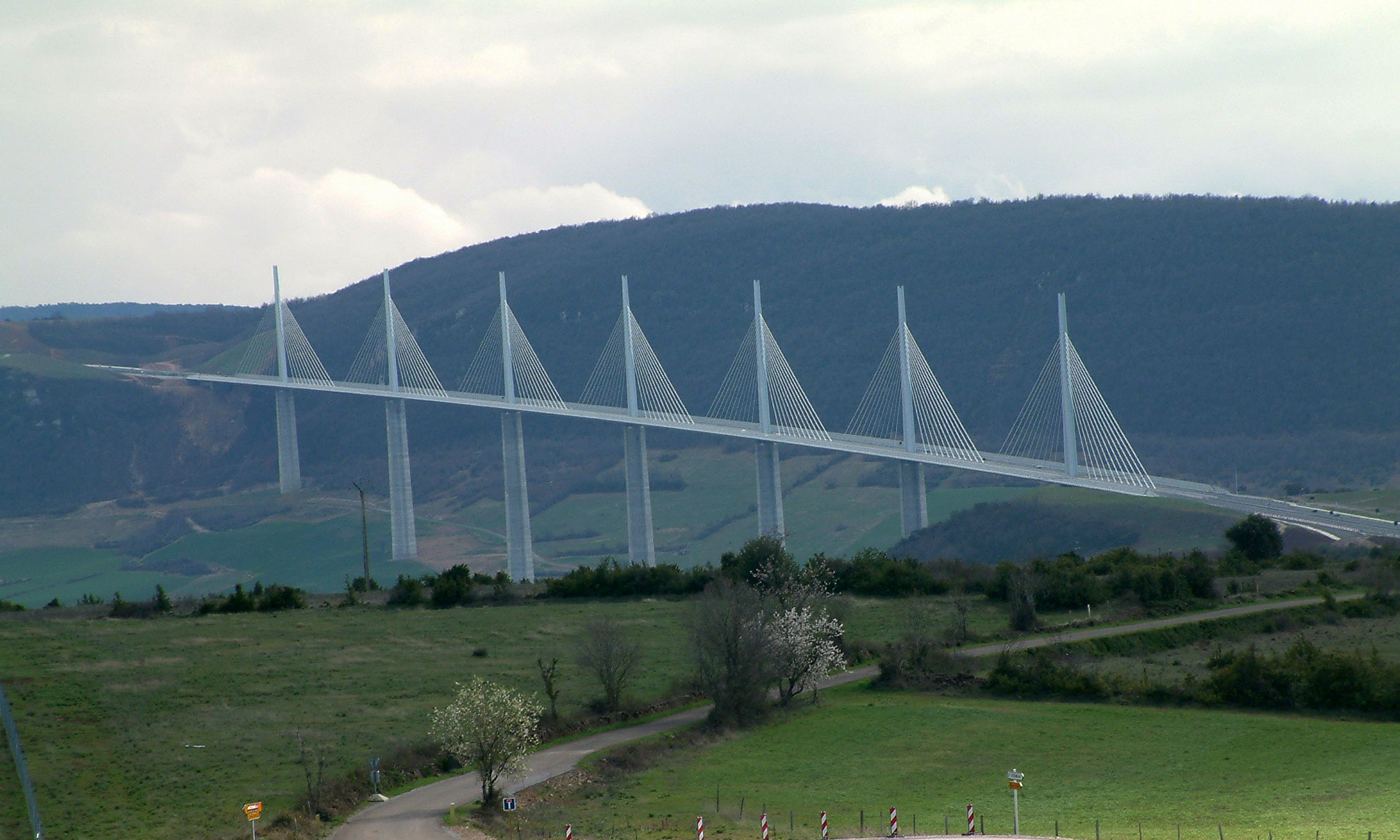
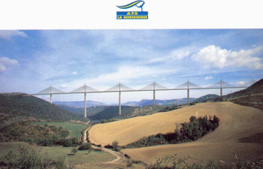
The Millau Viaduct, France. Connects Paris to Barcelona, 2.5 km long and 353 m high.
The Larzac plateau in southern France divides in two near Millau in the River Tarn valley. The area is famous for two things — Roquefort cheese and the notorious bottleneck at Millau on the A75 between Paris and Barcelona.
Now, however, relief has been provided by the recently opened Millau Viaduct, which at 1,125 ft. (343 m) high, is the tallest vehicle-carrying bridge in the world. A measure of its necessity is indicated by the fact that, until now, traffic jams in the congested old town routinely stretched back 12.5 to 18.7 mi. It is estimated that the bridge will cut journey times between 30 minutes and four hours, depending on the time of year.

Project Design
The road to construction was lengthy, with initial studies beginning in 1988. By June of the following year, the Center for Technical Equipment Studies in Aix-en-Provence had selected a design featuring a bridge, in part because it would avoid the need for a tunnel as well as causing little impact on the environment. In addition, although some valley residents protested a bridge, local politicians had made it plain for the previous 20 years or so that they viewed a bridge as the best answer to the difficulty.

Detailed studies began in 1993 and in 1994 a restricted design competition began, limited to submissions by five teams of architects. In summer 1996, the winning cooperative was announced, consisting of French engineers Sogelerg, based in Echirolles, Europe; Etudes Gecti of Villeurbanne, Simecscol, headquartered in Sevres; Consultant Michel Virlogeux, and British Architects Foster & Partners of London.
Viewed from a distance, the upper part of the Millau Viaduct resembles a line of billowing, cobwebby sails, presenting an airy and light appearance that effectively conceals its structural components.
Technical Challenges Overcome
In 2000 a competition for the concession and construction contract was announced. It was awarded to Paris-based Eiffage TP the following year.
Construction began on Oct. 16, 2001, with an estimated completion date of January 2005. The cost of the bridge was 300 million Euros ($390 million) plus another 20 million Euros ($26 million) to cover the construction of a toll station 3.7 mi. (6 km) north of the bridge.
The Millau Viaduct features six lanes plus hard shoulders. A multi-stayed structure with steel pylons and cables, its seven tuning-fork shaped hollow reinforced concrete piers support a steel deck 13.8 ft. (4.2 m) deep, approximately 105 ft. (32 m) wide and 1.5 mi. (2.5 km) long, standing 886 ft. (270 m) above ground level.
The height of these piers range from 254 ft. (77.6 m) up, the second and third rising to approximately 837 ft. (255 m) and 725 ft. (22l m), respectively. The tallest point of the bridge reaches a level approximately 4 percent higher than the Eiffel Tower. This was a multi-national project overseen by Eiffage du Viaduct de Millau.
In June 2002 Enerpac, based in Ede, The Netherlands, announced that it had been awarded the contract to supply a hydraulic system to carry out the massive task of placing the deck.
Enerpac’s solution to the complicated problem was to push the deck over seven temporary steel piers during the placement process; these piers were erected by hydraulic telescopic equipment designed and built by its Construction Center of Excellence in Madrid, Spain.
The first temporary pier was erected by a Potain K5/50C tower crane, one of seven that worked on the project. The cranes also assisted in placing formwork and pouring concrete, and according to Manitowoc, they handled approximately 36,000 tons (32,658 t) of reinforced steel and assisted in pouring 111,176 cu. yds. (85,000 cu m) of concrete.
The other six piers were raised by the Enerpac system, which was innovative and yet simple in design.
The equipment employed was a lifting mechanism consisting of four cylinders fed by individual pumps. Each was capable of a thrust of 511 tons (463 t), giving a total capacity of 2,044 tons (1,854 t). Placed inside a cuboid protective structure, these individually controlled hydraulic cylinders were anchored to supports fitted into toothed racks, which were notched at intervals of 3.3 ft. (1 m). Sensors incorporated into this equipment allowed for adjustments when raising the piers as would be needed for changes in temperature or wind speed.
To set a pier in place, its first freestanding segment was raised by the following method: Oil was pumped into the cylinders, thrusting rams against the segment and thereby raising it to the first slot on the toothed rack. Once there, it was locked in place with chocks, the rams withdrawn, and the process repeated until the segment was finally in place. At that point the hydraulic system, which moved in tandem with the pier, was returned to ground level by a crane, and the operation repeated, continuing in the same way until the complete pier was in place.
Placing the Deck
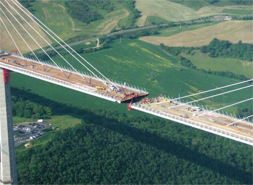
Once these temporary piers were erected, placement of the 36,000-ton (32,659 t) prefabricated deck (manufactured in Eiffel’s Construction Metallique factories at Lauterbourg and Fos-sur-Mer) began.
This painstaking process was accomplished by inching the deck forward with the aid of launching devices resting on sets of single-acting lock nut cylinders supporting both deck and device, plus retractable skates.
The cylinders controlled the balance of the skates on each pier, which in turn permitted compensation for any rotation of the deck during launching and, by correcting skate height as needed, also modified that of the deck during placement as necessary.
Because of its weight, as the deck was pushed further out, it began to point downwards. To counteract this effect, the launching system also included an additional independent nose recovery device placed on the end of the deck, allowing it to be pulled upwards or pivoted during operations.
All the hydraulic systems involved in moving the deck were operated from a central control center at the bridgehead. In addition, each pier had a local control panel permitting independent adjustment of the skates, provided any such adjustment had been approved by the central control center. This permission was only given after the latter had received approval from every local control panel, in order to synchronize the simultaneous pushing from all piers.
Moving the deck could be accomplished three ways: manual, semi-automatic and automatic. Manual mode was used for adjustments and any necessary instant corrections. In the semi-automatic mode, each movement was made step by step, or, in other words, raise, push, lower, and then withdraw. Automatic mode completed each entire launch cycle.
By the final phase of this part of the project, the southern side of the bridge had fielded 5,280 tons (4,790 t) of pushing capacity to place 1.1 mi. (1.7 km) of deck and the northern side fielded 2,400 tons (2,177 t) to move 0.44 mi. (.71 km) of deck. Each cycle of placement lasted four minutes and moved the deck 2 ft. (.6 m).
Placing the deck began in late February 2003. By March 26, 2004, the deck had progressed to the third pier. During the evenings of April 4 and 5, 2004, the deck arrived at the second pier, despite operations being somewhat delayed by weather conditions, which interfered with the equipment’s laser guidance system.
The third week of April saw the last launching of the deck from the northern side, at which point it had reached the mid-span mark and was protruding over the River Tarn. This left two more launch phases to be carried out from the southern side of the bridge. In all, 18 launches — six from the north side of the bridge and 12 from the south — were required to position the deck, with the last launch accomplished on May 28, 2004.
Once the deck was placed, the remaining work proceeded rapidly. Pylons were completed in July and the temporary piers dismantled in November, which also saw load testing carried out.
The Millau Viaduct opened a month ahead of schedule. On Dec. 14, 2004, French President Jacques Chirac inaugurated it by unveiling a plaque, while planes overhead trailed red, white, and blue smoke — the colors of the French flag.
Compagnie Eiffage du Millau Viaduct holds a 75-year operating concession in return for having funded the bridge’s construction. Guaranteed for 120 years, during construction the Millau Viaduct was viewed by approximately 400,000 visitors before it was formally opened to traffic on Dec. 16, 2004. The bridge is expected to carry approximately 28,000 vehicles daily during the summer months, and approximately 10,000 each day the remainder of the year.
Currently drivers using it pay a toll of 6 Euros ($7.5). Set against this, however, it is estimated the bridge will allow motorists to save gasoline costs, as well as up to 34 Euros ($44) in toll fees, because their journey has been shortened by 37.3 mi. (60 km).
Safety measures on the bridge include provision of an emergency telephone every .31 mi. (.49 km) as well as a 24-hour surveillance system incorporating such features as video recording of traffic, weather stations, and programmable message boards.
About the Company
Enerpac belongs to the Actuant group of companies, based in Milwaukee, WI. Enerpac specializes in the manufacture of high-pressure hydraulic equipment and systems for industry and construction uses, having begun by making water pumps for Ford T autos.
Recent projects include assisting in the relocation of the century-old Shanghai Concert Hall by providing equipment to lift the building off its original foundations and move it approximately 218 ft. (66.5 m).
The company also worked on the underground extension to Spain’s Prado Museum. After deconstruction of a nearby 16th century church, which is to be re-erected in the Prado’s extension, contractors dug a pit 151 ft. (46 m) long, 66 ft. (20 m) wide, and 66 ft. high on its site. Enerpac installed a system to shore up the sides of this excavation as well as monitor and adjust any instability caused to nearby foundations and highways.

The road deck for France's Millau Viaduct was built by launching its orthotropic steel superstructure from both ends of the bridge to meet over the Tarn River. The viaduct features about 1.61 kilometers (1 mile) of orthotropic steel superstructure. Photo: Groupe EIFFAGE.
Three-Dimensional View of Millau Viaduct, World's Highest Bridge
The 2,460 m long Millau Viaduct is a cable-stayed road bridge, and the road runs 270 m above the Tarn River at its highest.
This area is a part of the Massif Central, which extends from southern to central France. The area includes dry highlands with limestone deposits called "causse" in French. Deep gorges were formed, and there are some features peculiar to limestone deposits, such as limestone caves and potholes.* The A75, a 340 km long expressway linking Clermontferrand about 350 km south of Paris and Beziers near the Mediterranean Sea, runs primarily through the highlands in this area and crosses the Tarn Gorge. Since Millau Viaduct opened in December 2004, the A75 has been an important bypass linking Paris and the Mediterranean Sea.
| ||||||||||||||||||||||


The structural solution follows from the latter philosophical standpoint. The bridge has the optimum span between cable-stayed columns. It is delicate, transparent, and uses the minimum
material, which makes it less costly to construct. Each of its sections spans 350 metres and its columns range in height from 75 metres to 345 metres - higher than the Eiffel Tower - with the masts rising a further 90 metres above the road deck. To accommodate the expansion and contraction of the concrete deck, each column splits into two thinner, more flexible columns below the roadway, forming an A-frame above deck level. This structure creates a dramatic silhouette - and crucially it makes the minimum intervention in the landscape.
Millau Viaduct Website
> other website
Appointment Date: 1993
Construction Date: 2002
Completion Date: 2005
Statistics: Length: 2.5 km
Height: 280 m
Client: Department of Transport and Public Works of France
Consultants:
Chapelet-Defol-Mousseigne
Ove Arup and Partners


 Earth's magnetic field:
